DC field measurement performance
Individual axes (single-axis, X, Y, Z)
| Standard
|
| 35 T (350 kG) range | ±0.2% of rdg |
| 3.5 T (35 kG) range | ±0.15% of rdg |
| 350 mT (3.5 kG) range | ±0.15% of rdg |
| 35 mT (350 G) range | ±0.15% of rdg |
| Cryogenic
|
| 35 T (350 kG) cryogenic range | ±0.2% of rdg |
| 3.5 T (35 kG) cryogenic range | ±0.2% of rdg |
| 350 mT (3.5 kG) cryogenic range | ±0.2% of rdg |
3-axis magnitude accuracy
Calculated total field value based on measurement of all 3 axes.
| Standard
|
| 35 T (350 kG) standard range | ±0.40% of rdg |
| 3.5 T (35 kG) standard range | ±0.30% of rdg |
| 350 mT (3.5 kG) standard range | ±0.30% of rdg |
| 35 mT (350 G) standard range | ±0.30% of rdg |
| Cryogenic
|
| 35 T (350 kG) cryogenic range | ±0.40% of rdg |
| 3.5 T (35 kG) cryogenic range | ±0.40% of rdg |
| 350 mT (3.5 kG) cryogenic range | ±0.40% of rdg |
System measurement noise
Typical RMS measurement noise at zero field (teslameter and probe both contribute to measured noise, a realistic representation of measurement performance).
| | Averaging window |
| | 10 ms | 200 ms
(default) | 1 s | 10 s |
| 35 T (350 kG) standard range | 300 µT (3 G) | 70 µT (700 mG) | 30 µT (300 mG) | 10 µT (100 mG) |
| 3.5 T (35 kG) standard range | 6 µT (60 mG) | 1.2 µT (12 mG) | 0.6 µT (6 mG) | 0.17 µT (1.7 mG) |
| 350 mT (3.5 kG) standard range | 0.7 µT (7 mG) | 0.16 µT (1.6 mG) | 0.07 µT (0.7 mG) | 0.03 µT (0.3 mG) |
| 35 mT (350 G) standard range | 0.5 µT (5 mG) | 0.12 µT (1.2 mG) | 0.05 µT (0.5 mG) | 0.02 µT (0.2 mG) |
| 35 T (350 kG) cryogenic range | 300 µT (3 G) | 70 µT (700 mG) | 0.05 µT (0.5 mG) | 0.02 µT (0.2 mG) |
| 3.5 T (35 kG) cryogenic range | 38 µT
(380 mG) | 8.5 µT
(85 mG) | 3.8 µT
(38 mG) | 1.2 µT
(12 mG) |
| 350 mT (3.5 kG) cryogenic range | 4.4 µT
(44 mG) | 1 µT
(10 mG) | 0.44 µT
(4.4 mG) | 0.14 µT
(1.4 mG) |
TruZero™ residual offset
Remaining detectable measurement offset (observed at zero field and expected to be present at higher fields as well)
| | Individual axes (single-axis, X, Y, Z) | 3-axis magnitude |
| Offset within ±5 °C of probe calibration temperature | ±3.5 µT (±35 mG) | ±7 µT (±70 mG) |
| Typical temperature coefficient beyond ±5 °C of probe calibration temperature | ±0.3 µT/°C (±3 mG/°C) | ±0.6 µT/°C (±6 mG/°C) |
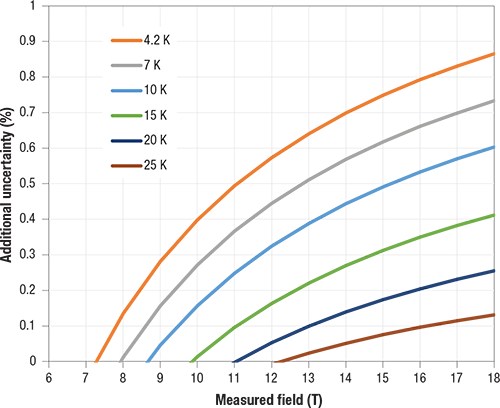
Quantum Hall effect additional uncertainty
When operating at high field at cryogenic temperatures, the Shubnikov-De Hass effect causes small oscillations in the effective Hall sensor sensitivity. The following plot outlines the additional uncertainty values that should be expected.