lipix

Calibration accuracies

ULT Rox™ sensors go through an intensive cryogenic calibration process. Each sensor comes with a downloadable calibration curve and traceability to NIST standards. Figure 1 demonstrates an example of roll‑over behavior of a calibrated ULT Rox. Calibration ensures a roll-over point beyond the calibration limit, ensuring readings down to 5 mK. It is critical to follow the installation instructions to replicate the calibration environment and wait for the sensor to fully cool down to meet accuracies at 5 mK.

5 mK1±1.2 mK
7 mK1±0.8 mK
10 mK1±1 mK
20 mK1±2 mK
50 mK1±4 mK
1.4 K2±16 mK
4.2 K2±16 mK
10 K2±30 mK

1Calibration done utilizing a noise thermometer
2[(Calibration uncertainty)2 + (reproducibility)2]0.5

Example of roll-off curve of one ULT Rox sensor

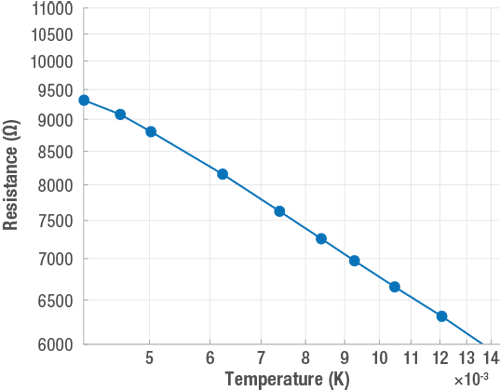
Figure 1 Example of roll-off curve of one ULT Rox sensor

Temperature sensitivity

At 5 mK, ULT Rox devices typically exhibit a sensitivity of approximately 300,000 ohms/K, indicating a high responsiveness to temperature changes. Additionally, the resistance at 5 mK is around 10 kΩ. This high sensitivity means that even small temperature fluctuations result in significant changes in resistance, making the device highly effective for precise measurements in ultra-low temperature environments.

Typical sensitivity Ω/K

Typical sensitivity over temperature for ULT Rox sensors

Figure 2 Typical sensitivity over temperature for ULT Rox sensors, showing increases responsiveness at lower temperatures

Typical resistance Ω

Typical resistance curve of a ULT Rox™ sensor

Figure 3 Typical resistance curve of a ULT Rox™ sensor varies from 10,000 Ω to 2,000 Ω over its operational temperature range

Performance specifications

Temperature range
(RX-102B-RS-0.01B)
5 mK to 40 K
Resistance range10 kΩ to 20 kΩ
Recommended excitation320 mV at 0.05 K to 0.1 K
63 mV at 0.1 K to 1 K
10 mV or less for temp > 1 K
Short-term stability4±15 mK at 4.2K
Long-term stability±30 mK/year at 4.2 K
Thermal response time0.5 s at 4.2 K
Maximum power before damage10-5 W, 0.1 mA or 1 V (whichever is lowest)
Dissipation at rated excitation (typical)7.5-8 W at 4.2 K

3Recommended excitation for T < 1 K based on Lake Shore calibration procedures using a 372 AC resistance bridge temperature controller.
4Short-term reproducibility data is obtained by subjecting sensor to repeated thermal shocks from 305 K to 4.2 K.

Physical specifications

Lead wireTwo-lead, no polarity
Package optionsRS
Mass5.36 g
Mounting
M3 or #6 brass screw (included)
Minimum washer OD of 7 mm (included)
N-Grease (not included)
Wire36 AWG copper, insulated with heavy build polyimide to an overall diameter of 0.152 mm (0.006 in), 40 cm (16 in) long. Lead ends tinned with 63/37 SnPb solder
Soldering standardJ-STD-001 Class 2

RX-102B-RS

RX-102B-RS dimensional drawing

Lead extensions

ULT Rox™ come standard with approximately 40 cm (16 in) lead wires. Extensions can be added to your device to extend lead length, with a variety of wire types available to suit your application. Below are the most common configurations. Refer to the Lead Extensions datasheet for the complete list.

-QTQuad-Twist™, 36 AWG, 2 m
-QLQuad-Lead™, 32 AWG, 2 m

Included mounting hardware

Each filtered ULT Rox™ sensor ships with metric brass screws. Brass screws are optimal for thermal conductivity and replicates the calibration environment for accurate measurements. Proper mounting is critical to meet specifications; see installation instructions.

  • M3 brass fastener, 12 mm length
  • M4 brass fastener, 14 mm length
  • M3 washer
  • M4 washer
  • Apiezon N grease is required for installation (not included)

Temperature controller

A 372 temperature controller is required to take readings below 50 mK. Add a 3726 scanner card to increase the number of channels from 2 to 17 and provide a fully guarded signal path.

372-t

372NAC resistance bridge temperature controller
372SAC resistance bridge temperature controller with 3726 scanner