Attaching discrete Hall sensors to Lake Shore gaussmeters
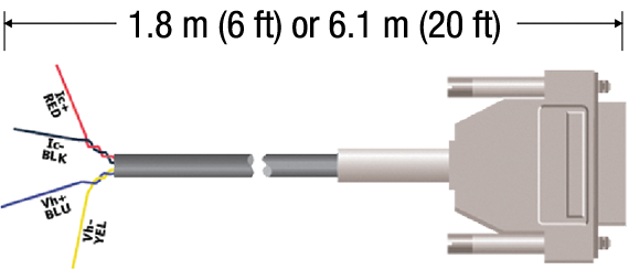
Lake Shore provides cable assemblies containing the necessary electronic memory (EEPROM) to interface an InAs Hall sensor to a gaussmeter. This allows users to assemble a Hall sensor into a difficult-to-access area prior to gaussmeter attachment. The figure
below shows the general cable configuration. While convenient, this method provides less than optimum performance. Because of the intricacies involved with proper calibration, the user is responsible for the measurement accuracy. A probe fully calibrated
by Lake Shore is always suggested.
Certain Hall sensor sensitivity constraints are applicable:
—Sensitivities between 5.5 and 10.5 mV/kG at 100 mA control current.
—Sensitivities between 0.55 and 1.05 mV/kG at 100 mA control current.
For Model 475, 455, and 425 gaussmeters
1.8 m (6 ft) and 6.1 m (20 ft) cables are available.
Models 475, 455, and 425 offer the convenience of front-panel programming. No external computer is required. The Hall sensor serial number and single-point sensitivity are directly entered using the keypad.
For legacy Model 460, 450, and 421 gaussmeters
The connection of discrete Hall sensors to these instruments is no longer supported. Contact Service for ongoing support of these instruments.
What is a Hall effect sensor?
A Hall sensor is a solid-state device that detects and measures magnetic fields using the Hall effect. When an electric current flows through a conductor or semiconductor and a magnetic field is applied perpendicular to that current, a small voltage—called the Hall voltage—is generated at right angles to both the current and the magnetic field. This voltage is directly proportional to the strength of the magnetic field, allowing the sensor to quantify it.
What does a Hall sensor do?
In practical applications, Hall sensors are used to detect the presence, strength, and direction of magnetic fields. They are widely employed in systems that require contactless sensing, such as determining the position or speed of rotating objects in brushless DC motors, measuring current in power electronics, or detecting proximity in devices like smartphones and industrial automation systems. Because they have no moving parts, Hall sensors are highly reliable, durable, and suitable for harsh environments. Their fast response time and clean, non-mechanical operation make them ideal for applications ranging from automotive systems and robotics to consumer electronics and scientific instrumentation.
What is the difference between a CT and a Hall sensor?
The main difference between a current transformer (CT) and a Hall sensor lies in how they measure current and the types of current they can detect.
A current transformer is an electromagnetic device that measures alternating current (AC). It works by using a magnetic core and a secondary winding to produce a scaled-down replica of the primary current. CTs are highly accurate for AC measurements and are commonly used in power distribution systems, energy meters, and industrial monitoring. However, they cannot measure direct current (DC), as they rely on the changing magnetic field produced by AC to induce a current in the secondary coil.
In contrast, a Hall sensor uses the Hall effect to measure both AC and DC currents. It detects the magnetic field generated by the current flowing through a conductor and converts it into a voltage signal. Because it senses the magnetic field directly, a Hall sensor can measure static (DC) as well as dynamic (AC) fields. This makes it more versatile than a CT, especially in applications like battery monitoring, electric vehicles, and power electronics where DC current measurement is essential.
CTs are ideal for high-accuracy AC current measurement in power systems, while Hall sensors offer broader functionality, including DC current sensing, with the added benefits of compact size and contactless operation.