
Hall (magnetic) sensors
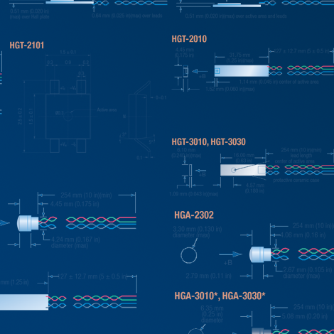
- Multiple packages available
- Options for high stability or sensitivity
- Compatible with Lake Shore 400 Series gaussmeters
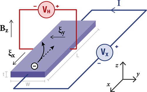
Hall effect sensors provide a convenient method for measuring or detecting magnetic fields electronically by providing an output voltage proportional to magnetic flux density. As implied by its name, this device relies on the Hall effect. The Hall effect is the development of a voltage across a sheet of conductor when current is flowing and the conductor is placed in a magnetic field.
Lake Shore offers a range of Hall sensors aimed at various applications. In all cases, these sensors go beyond the application of simple magnetic presence detection, such as those used in encoders, contactless switches, and electronic compasses. Lake Shore sensors are useful for field measurement applications, where field value, direction, and polarity are of interest.
Simplify your field measurements
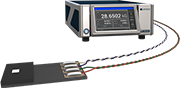
- Connect sensor directly to a Lake Shore teslameter and read field values directly
- Superior accuracy with full calibration, temperature, and linearity compensation
Hall sensor selection guide
Lake Shore Hall sensors offer the flexibility to power and read the resulting hall voltage with your own instrumentation.
| InAs—stable | InAs—sensitive | GaAs | |
| What makes this work? Words to impress your boss | Indium arsenide bulk material, doped for high stability | Indium arsenide bulk material, doped for high sensitivity | Gallium arsenide thin film |
| Temperature range An advantage of non-silicon-based Hall sensors is the opportunity for use in more extreme temperatures | 1.5 K to 375 K (-271.5 °C to 102 °C) | 208 K to 373 K (-65 °C to 100 °C) | 233 K to 402 K (-40 °C to 125 °C) |
| Interchangeability Ability to operate multiple sensors with identical drive and measurement setups | Poor—sensitivity range is large enough to require knowledge of the average sensitivity value | Poor—sensitivity range is large enough to require knowledge of the average sensitivity value | Poor—sensitivity range is large enough to require knowledge of the average sensitivity value |
| Ruggedness Ability to survive shock and vibration | Poor | Poor | Good |
| Lake Shore instrument compatibility Gaussmeter/teslameter compatibility for these sensors, allowing for field values to automatically be displayed by the instrument | 425 or 475 gaussmeter using HMCBL cable; field conversion accomplished with single sensitivity value only, meaning linearity and temperature compensation is not carried out by the gaussmeter | 425 or 475 gaussmeter using HMCBL cable; field conversion accomplished with single sensitivity value only, meaning linearity and temperature compensation is not carried out by the gaussmeter | None |
| Planar Hall effect Physical property related to Hall element thickness that introduces measurement error when the field is in-plane with the sensor element | Significant—bulk material produces enough of a planar Hall effect that fields with known directions are required for accurate measurements | Significant—bulk material produces enough of a planar Hall effect that fields with known directions are required for accurate measurements | Some—thin-film elements may exhibit small amounts of planar Hall effect error |
| Sensitivity at nominal current Impacts measurement accuracy and resolution—a higher number is better | 5.5 to 11 mV/T | 55 to 125 mV/T | 110 to 280 mV/T |
| Sensitivity temperature coefficient Impacts accuracy during large temperature shifts | 50 ppm/°C | 800 ppm/°C | 600 ppm/°C |
| Nominal drive current The recommended excitation level for these sensors | 100 mA | 100 mA | 1 mA |
| Typical input resistance Useful when selecting the drive circuit | 2 Ω | 2 Ω | 750 Ω |
| Typical input resistance temperature coefficient An additional source of measurement error if using a voltage source (rather than current source) to power the sensor | 0.15%/°C | 0.18%/°C | 0.2%/°C |
| Best offset voltage (field equivalent) An error component that has a bigger impact at small fields | ±50 µV (4.5 mT) | ±75 µV (0.6 mT) | ±2.8 mV (10 mT) |
What is a Hall effect sensor?
A Hall sensor (or Hall generator) is for measuring magnetic fields. It works on the principle of the Hall effect, which causes a voltage difference (Hall voltage) to develop across the conductor, proportional to the strength of the magnetic field.
What does a Hall sensor do?
A Hall sensor detects magnetic fields and converts them into an electrical signal using the Hall effect. When a magnetic field is applied perpendicular to an electric current in the sensor’s conductive element, a voltage known as the Hall voltage is generated. This allows the sensor to measure position, proximity, rotational speed, and current without physical contact, making it ideal for applications in scientific instruments, motors, and control systems.
What is the difference between a Hall effect sensor and a magnetic sensor?
A Hall effect sensor is a type of magnetic sensor that uses the Hall effect to generate a voltage when a magnetic field is applied perpendicular to an electric current in a conductor. Magnetic sensors is a broader category that includes Hall sensors as well as other technologies such as magnetoresistive and fluxgate sensors. While all detect magnetic fields, Hall sensors are widely used for their simplicity, durability, and cost-effectiveness in position, speed, and current sensing applications, whereas other magnetic sensor types may be chosen for specialized requirements.
What are the three common causes of sensor failure?
The three most common causes of sensor failure are environmental factors, electrical issues, and mechanical wear. Environmental factors include exposure to extreme temperatures, moisture, and contaminants that degrade sensor components. Electrical issues such as voltage spikes and electromagnetic interference can damage sensitive electronics. Mechanical wear occurs over time due to vibration, shock, or physical stress on connectors and housings. Preventive measures include protective enclosures, surge protection, and regular maintenance.