PS-HM-8425 software
Software features
The fully integrated HMS software features a Windows® graphic menu-driven interface for system operation, data acquisition, and analysis. Use it to control magnetic field, sample temperature, and sample excitation while delivering a comprehensive collection of measurement capabilities. With the software, you have complete control over measurement parameters and can change them in real time. When combined with environmental settings like temperature, experimental parameters can be quickly determined.
Define and save specifications and experimental configurations as well as record and display data in laboratory and SI units for further analysis. Processed data can be displayed in graphical and tabular format. Also, with the software’s SQL reporting capabilities, data and plots can be printed or exported directly to a Microsoft Excel® spreadsheet as well as PDF or Microsoft Word® documents.
Supports van der Pauw and Hall bar measurements
To measure sample sheet resistivity, the 8400 Series supports van der Pauw and Hall bar measurement geometries. The Hall bar method uses one dimensional current flow approximation. You can also measure samples with gated Hall bars to account for gate bias—important for measurement of device-level material.
Measure Hall density in a channel as a function of gate voltage and, as you change the gate voltage, create more or fewer carriers. The system’s program mode makes it easy to conduct gated Hall bar measurements. For instance, you can set up a loop with varying temperatures and gate voltages and easily perform a Hall measurement with the software.
Easy setup for running temperature loops
The system supports variable temperature measurements, enabling you to start and end at your convenience. It also enables you to perform time loops, so you can repeat Hall measurements according to a preset schedule. (Manual adjustment of the probe station’s heat switch is required at several temperature points.) You can also program it to insert a resistance measurement into a sequence of Hall measurements.
Creating a new variable temperature Hall measurement can be done with just three clicks of a mouse. Once the measurement is set up, the software continuously monitors the sample temperature, and when it reaches the next trigger temperature, executes the measurements placed inside the temperature loop. While the measurements are in progress, the sample temperature continuously changes.
Commands enable you to “Go to Temperature,” “Go to Field,” and “Go to GBV” (gate bias voltage). You can also program it to “Wait,” that is, start a measurement then have the system pause and settle before continuing. This way, you have the flexibility to automate and customize your experiment procedure.
Toolbox with resistance utility
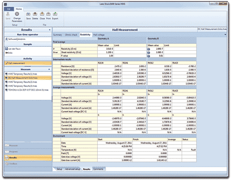
Example of a DC measurement results screen
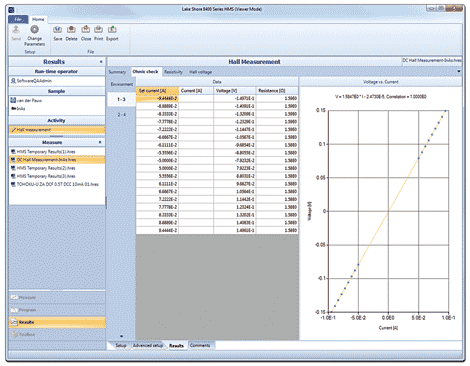
Example of an ohmic check
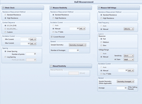
Hall measurement setup is used to define the three basic steps in a Hall measurement. These steps include checking the quality of your sample contacts, measuring the resistivity of your sample and measuring the Hall voltage.
8400 Series software capabilities | ||
Sample types
Direct measurements
Calculated measurements
Field control
Temperature control
| User-defined programs
Toolbox
Reports and exports
| |
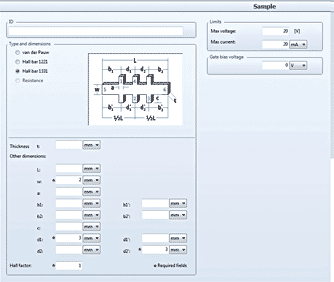
Define your sample geometry and contact arrangement, as well as the maximum voltage and current applied to it. Sample definition parameters include thickness and sample dimensions. You can assign sample identifications and add user
comments. An ASTM compliance check can also be performed.
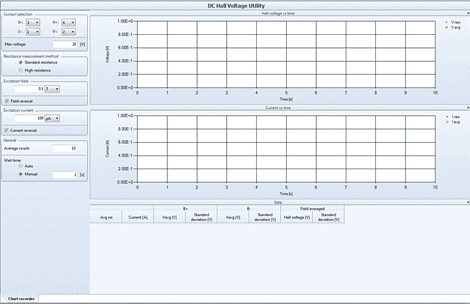
The toolbox includes utilities that allow you to determine measurement parameters, collect and log data, and display the data on screen as a chart recorder. You have complete control over the measurement parameters and can change them in real-time. When combined with environmental settings like temperature, experimental parameters can be quickly determined.
QMSA software support
The Model 8425 system can also be used with our Quantitative Mobility Spectrum Analysis (QMSA) software package for advanced multi-carrier analysis. With it, you can acquire detailed information about transport properties of the individual carriers of materials or devices, going beyond what’s possible with single field Hall measurements. It’s particularly useful for resolving individual carrier mobilities and densities in quantum wells and high electron mobility transistors (HEMTs).
This software automatically segregates the mobility spectrum for each carrier species (electrons and holes) that comprise a multilayer or multi-carrier material, including heterostructures, quantum wells, and multiply doped materials. Input parameters for the software analysis include Hall coefficient, resistivity, and magnetic field. Output parameters include conductivity spectra as a function of mobility, number of carriers (peaks in the mobility graph), density, mobility, and sign of each carrier.


